How to 3D Print an Aeroplane - Day 8 - Firewalls and sectioning the fuselage.
- Jon
- Apr 9, 2020
- 3 min read
I'm going to start sectioning the fuselage. I’ll start with the motor mounts, known sometimes as firewalls (so named because in a real aeroplane it would be designed to stop an engine fire blowing into the cockpit). It is an easy starting point, defined by the dimensions of the motor. I know from a previous model that I need 24mm depth to mount my motors. I find the easiest way to split any body is to create a sketch with a large circle, patch the circle in the surface work space, then split the body.
After splitting off the cowlings I have shelled them (the shell tool), these can be glued on after we have mounted the motors. Doing it this way leaves the firewall attached to the main body of the aircraft which is handy as all the force from the prop is acting on the mass (the plane) through this join. Its not ideal if the motor flies off the aircraft in flight. It also defines which part of the fuselage will be in contact with the build plate for when we start printing. This leads us to the first important limitation of 3D printing to think about.
Bridging. As the name implies this is when we try to print in mid air, with nothing for the plastic to adhere too. It is possible to bridge small gaps but as the bridge gets bigger it gets messier and less reliable. When printing aircraft where the aim is for thin, lightweight walls the situation is even worse as we don’t have successive layers to hide the problems.
One solution is to use support structures, however this greatly lengthens the print time, increases filament cost and can be a pain in the backside trying to remove them. Another is to shorten the bridge, using a curve. 3D print people often talk about the 45 degree rule (more of a guideline than a rule). Finally, sometimes it’s possible turn the bridge upside down, so that the bridged section is in contact with the build plate, hey presto, no bridge to worry about anymore. This is especially effective with 3d printed aircraft as we have to slice them up and glue the components together anyway. Here is an example:


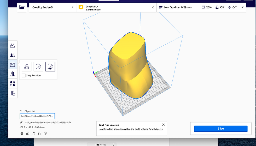
Printed this way round would require a large bridge at the top of the model - or a supporting structure the whole way up the inside!
So instead, if we print it the other way round we save all that agro.


Now, this is all bleeding obvious - especially looking at it like with a pre sectioned model. It is less obvious when you are sectioning the model in the first place, and a real face palm moment when you come to print your model, and find that you didn't think about it at the time and have to go back to the (digital) drawing board.
Hopefully as we progress the reasons behind the sectioning I use will become apparent. But feel free to ask questions along the way.
By the way, a great resource for 3D printing troubleshooting is www.all3dprint.com.
In the screencast you will see that we have ended up with 3 main fuselage sections - the nose, including a 12mm firewall for the fwd engine to be attached to - the central fuselage, which the wing will somehow attach to - and the rear fuselage, which includes the aft engine firewall. On top of this we have a fwd and rear engine cowlings.

Comments